In-Office Crown and Artificial Gingiva Design for Replacement of Lost Interdental Papillae Using SmileFy
Workflow Summary
Upload & Calibrate
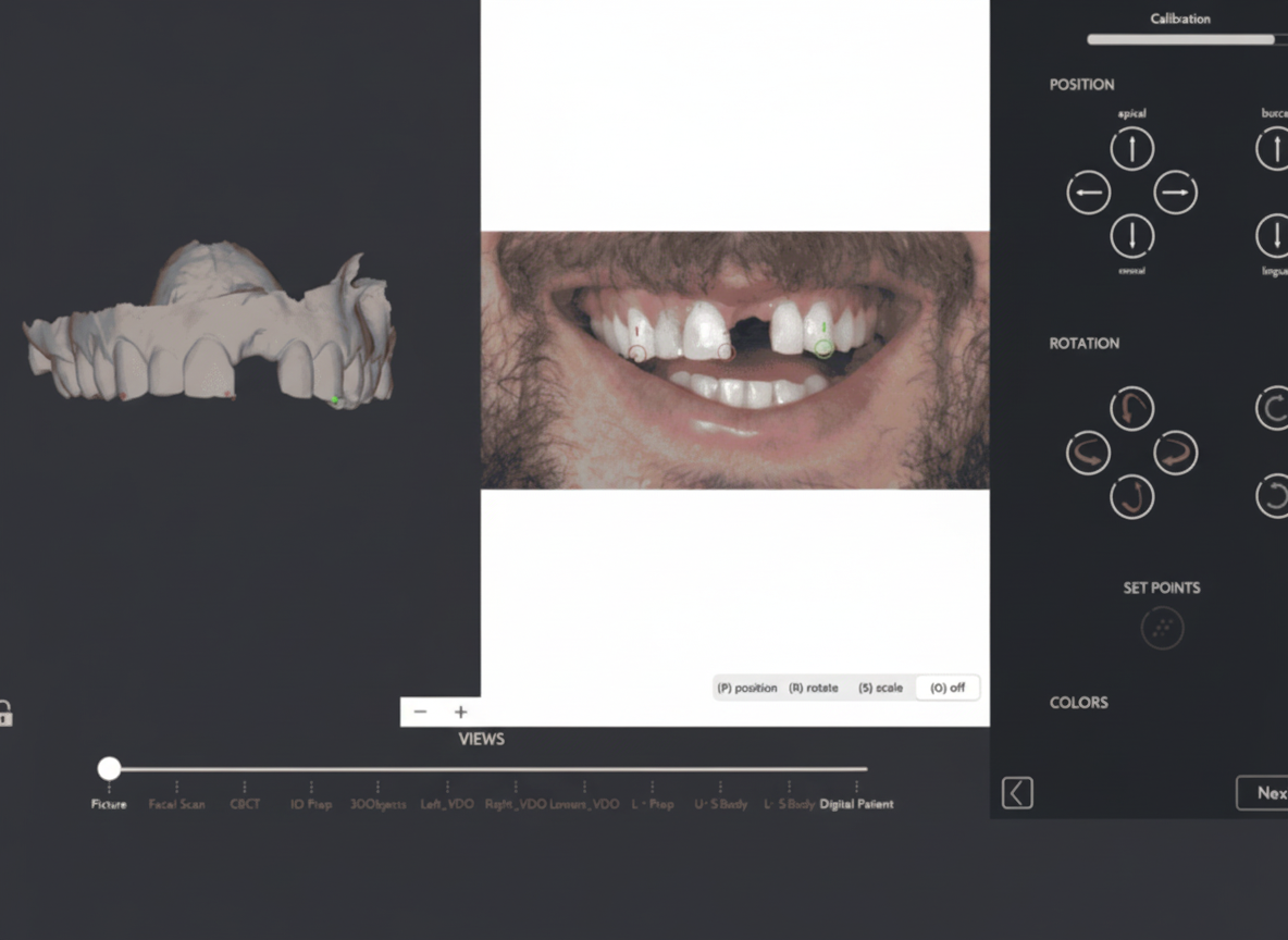
Upload full-face photo + upper/lower arch STL scans → calibrate (superimpose) in SmileFy to establish the facially generated reversed treatment plan.
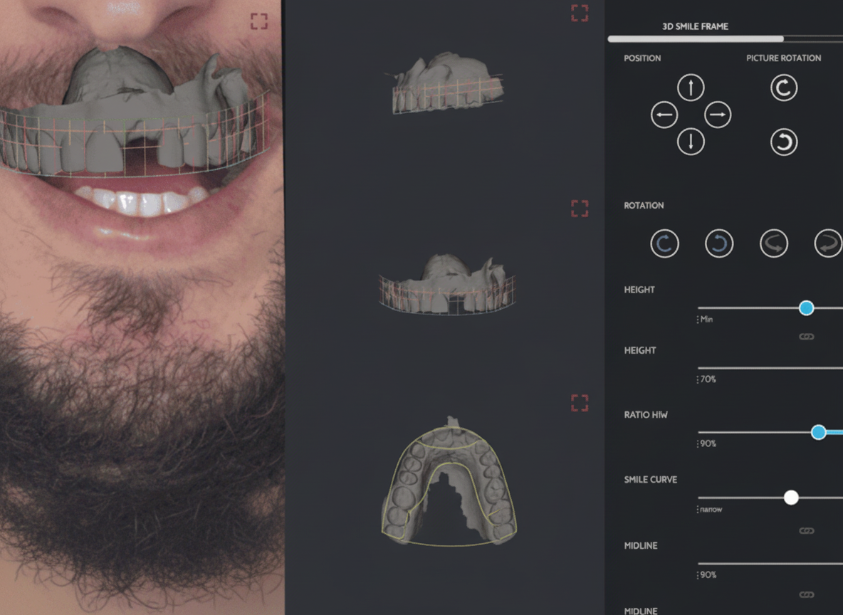
3D Smile Frame
Set tooth proportions, width, height, and midline over the intraoral scan.
Dental Chart
Select the single unit (or full arch); auto-place the chosen 3D tooth template onto the STL.
Template & Design
Select and apply the anatomical artificial gingiva architecture to the design.
Mesh Editor
Freehand-refine gingival contour with digital brushes; verify contact points, emergence profile, and restoration thickness.
Union / Fuse
Export two merged STL variants: (A) tooth + artificial gingiva; (B) tooth + artificial gingiva + upper arch model.
STL Export
Send to lab for biocopy into CAD software (exocad / 3Shape) to fabricate surgical implant guide, crown temp for immediate loading, or final crown with artificial gingiva.
Prosthetic papilla fill eliminates visible black triangles; fused STL files provide the lab with a single unambiguous biocopy reference for all downstream manufacturing paths.
Overview
Lost interdental papillae — clinically visible as "black triangles" (open gingival embrasures) — are a common and aesthetically significant sequela of periodontitis, implant placement, aggressive restorative preparation, or natural aging-related crestal bone loss. Once the interproximal papilla is absent, non-surgical reconstruction is unpredictable; surgical papilla regeneration has limited evidence and high technique sensitivity, and composite augmentation is often insufficient for single-crown implant sites where bone support is structurally absent.
SmileFy's 3D AI workflow provides a chairside prosthetic solution: a digitally designed single crown with an integrated artificial gingiva component that fills the interdental void with a contoured, lab-fabricable soft-tissue surrogate. The design is facially driven, generated directly over the superimposed intraoral scan, and exported as fused STL files that are immediately biocopy-ready in any major dental CAD platform.
The result is a predictable, minimally invasive, same-visit design workflow that replaces unreliable soft-tissue management with a precisely engineered prosthetic solution — with full patient visualisation and direct laboratory handoff built in.
Key Terms
Interdental papilla / Black triangle — The triangular gingival tissue occupying the embrasure space between adjacent teeth. When absent or receded, the resulting open embrasure is termed a "black triangle" (open gingival embrasure, OGE).
Artificial gingiva / Gingival mask — A prosthetic component — fabricated in ceramic, composite resin, or pink-shaded material — that replicates missing soft-tissue volume. In the SmileFy workflow, the artificial gingiva is designed digitally and integrated with the crown STL before laboratory export.
Biocopy — A CAD/CAM manufacturing technique in which a pre-existing digital form (the SmileFy-designed crown + gingiva STL) is used as the reference object to mill or print the definitive restoration, preserving the designed contours with high dimensional accuracy.
Union / Fuse — The SmileFy function that merges two or more separate mesh objects (e.g., crown STL + gingiva STL) into a single watertight solid for export. Fusing eliminates inter-object gaps that would cause errors during biocopy or 3D printing.
Emergence profile — The three-dimensional contour of a restoration as it exits the soft tissue margin. Correct emergence profile is critical for papilla support: an over-contoured profile compresses the papilla; an under-contoured profile allows tissue collapse into the embrasure.
Indications and Case Selection
This workflow is the treatment of choice when all of the following conditions are present:
Single-unit implant crown or conventional crown at a site with documented interdental papilla loss and absent or severely reduced interproximal bone support.
Interproximal bone crest ≥ 3 mm apical to the contact point of the adjacent teeth (Tarnow Classification Class II–III), making natural papilla regeneration biologically implausible.
The patient is seeking a fixed prosthetic solution and accepts a restoration with a pink/gingival-coloured component.
The patient presents with adequate oral hygiene compliance and is willing to adopt modified interproximal cleaning tools (interdental brushes, water flossers).
The restorative team has access to digital scanning (intraoral scanner) and a CAD/CAM-capable laboratory (exocad or 3Shape compatible).
Step-by-Step Clinical Workflow
Step 1 — Photo and Intraoral Scan Upload + Calibration (~5 min)
Upload the facial photo and both arch STL files. Use the calibration tool to superimpose (align) the intraoral scan onto the facial photograph, establishing a facially generated reversed treatment plan. Ensure the arch scan is saved in maximum intercuspation without bite registration geometry, which would distort superimposition. Confirm midline and smile arc alignment visually before proceeding.
Pro Tip: The photo can be taken with your DSLR camera or even with your SmileFy iPhone or iPad. When saving, make sure to save in occlusion without including the bite registration files.
Step 2 — 3D Smile Frame (~5 min)
The 3D Smile Frame outlines the intraoral scan and sets the future three-dimensional tooth positions. Adjust the frame to define the target width, height, and midline for the crown unit within the context of the full smile arch. Reference the facial midline established in Step 1. Tooth width-to-height ratio for anterior crowns typically targets 75–85%. Verify that the proposed incisal edge position respects the lower lip curvature in the facial photograph.
Step 3 — Dental Chart and Tooth Template Selection (~5–8 min)
Use the Dental Chart to select the specific tooth unit(s) for this case. The selected 3D tooth template is automatically placed onto the STL within the dimensional envelope set by the Smile Frame. Select from SmileFy's library of natural-morphology 3D tooth templates. For implant sites with black triangle presentation, prioritise templates with narrower cervical emergence profiles to allow space for the gingival component.
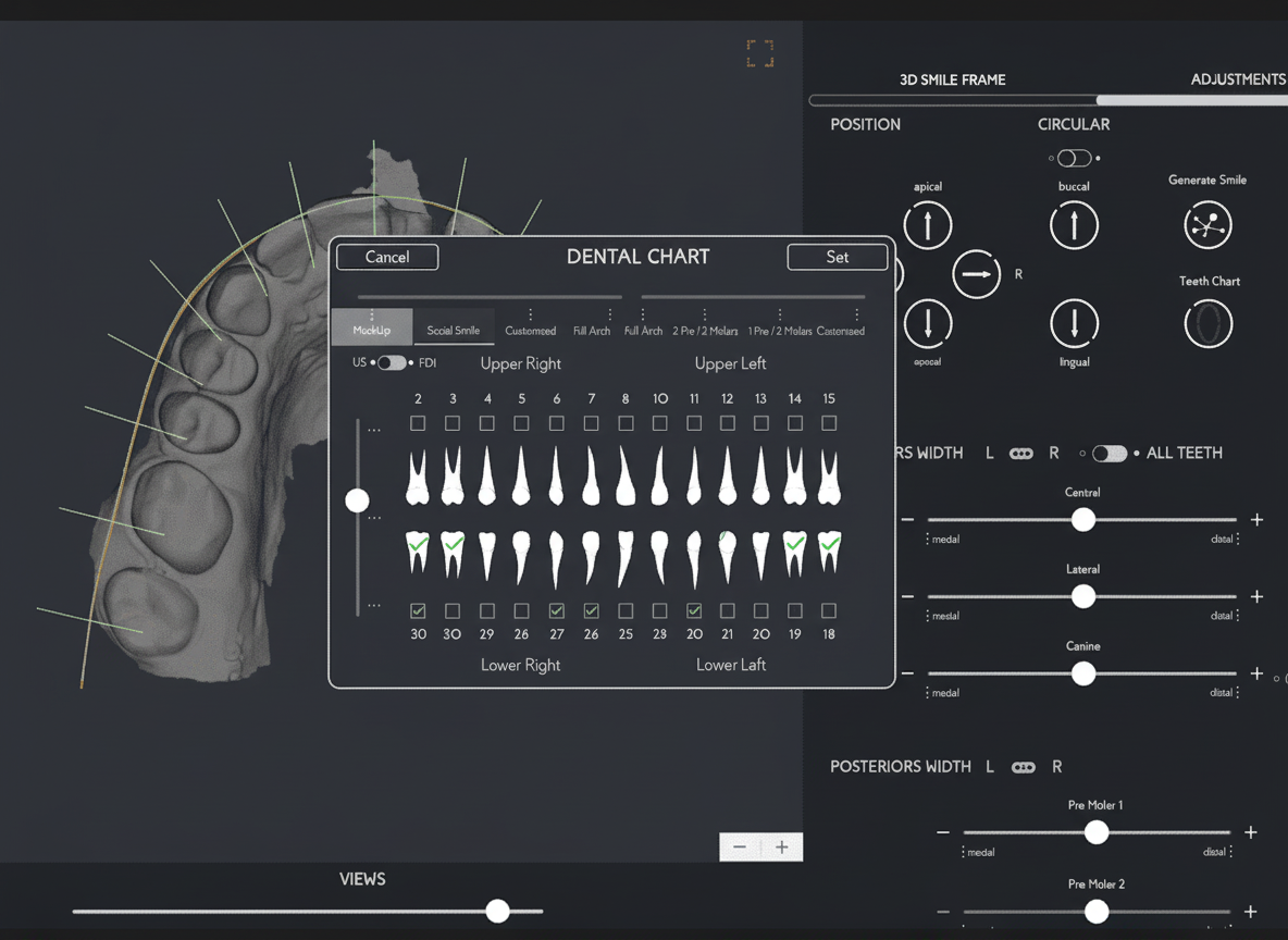
The vast selection of natural-looking 3D teeth templates can be tried on virtual diagnostic wax-up and fully adjusted in proportion and form. Different views of the 3D project are accessible, allowing the smile designer to verify position from various angles and check the buccal volume of the anterior teeth.
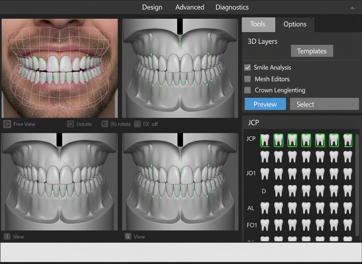
Step 4 — Template & Design (~3–5 min)
Select and apply the artificial anatomical gingiva template to the design. The template provides the initial three-dimensional gingival architecture — including papilla form, gingival zenith position, and cervical contour — as a starting point for Mesh Editor refinement. Choose a template whose papilla height approximates the depth of the black triangle void at the treatment site.
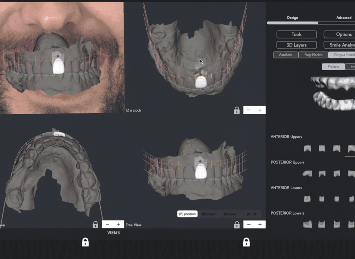
Step 5 — Mesh Editor Refinement (~10–15 min)
Use the Mesh Editor's freehand digital brushes to refine the artificial gingiva contour to the specific negative space of this patient's case. Add volume to fill the interdental void, remove excess in areas of over-contouring, and smooth transitions at the gingival margin and the tooth-gingiva interface. Verify contact point geometry, restoration thickness, and emergence profile.
Brush size: Use smaller brush sizes (precision mode) at the papilla tip and margin areas; larger brush sizes for broad convexity additions mid-body.
Brush strength: Low-to-medium for smoothing; higher for rapid volume addition. Apply smoothing brush last to eliminate tool artefacts before export.
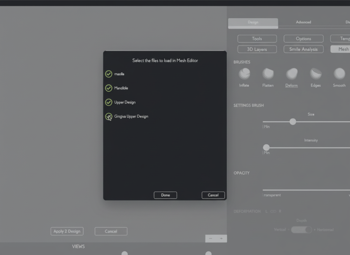
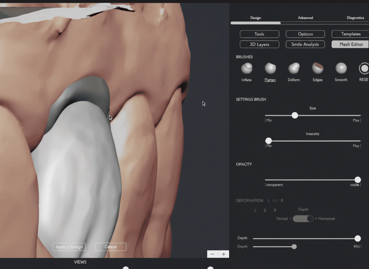
Quality targets to verify before proceeding to fusion:
Contact point in the incisal third (height ≥ 3–4 mm from gingival margin)
Minimum crown thickness ≥ 1.5 mm for zirconia; ≥ 1.0 mm for lithium disilicate
Minimum artificial gingiva thickness ≥ 1.0 mm at the papilla tip; ≥ 1.5 mm through the body
Occlusal clearance ≥ 1.5–2.0 mm from opposing dentition
Subgingival emergence angle concave-to-straight (< 30°)
No mesh self-intersections or open edges
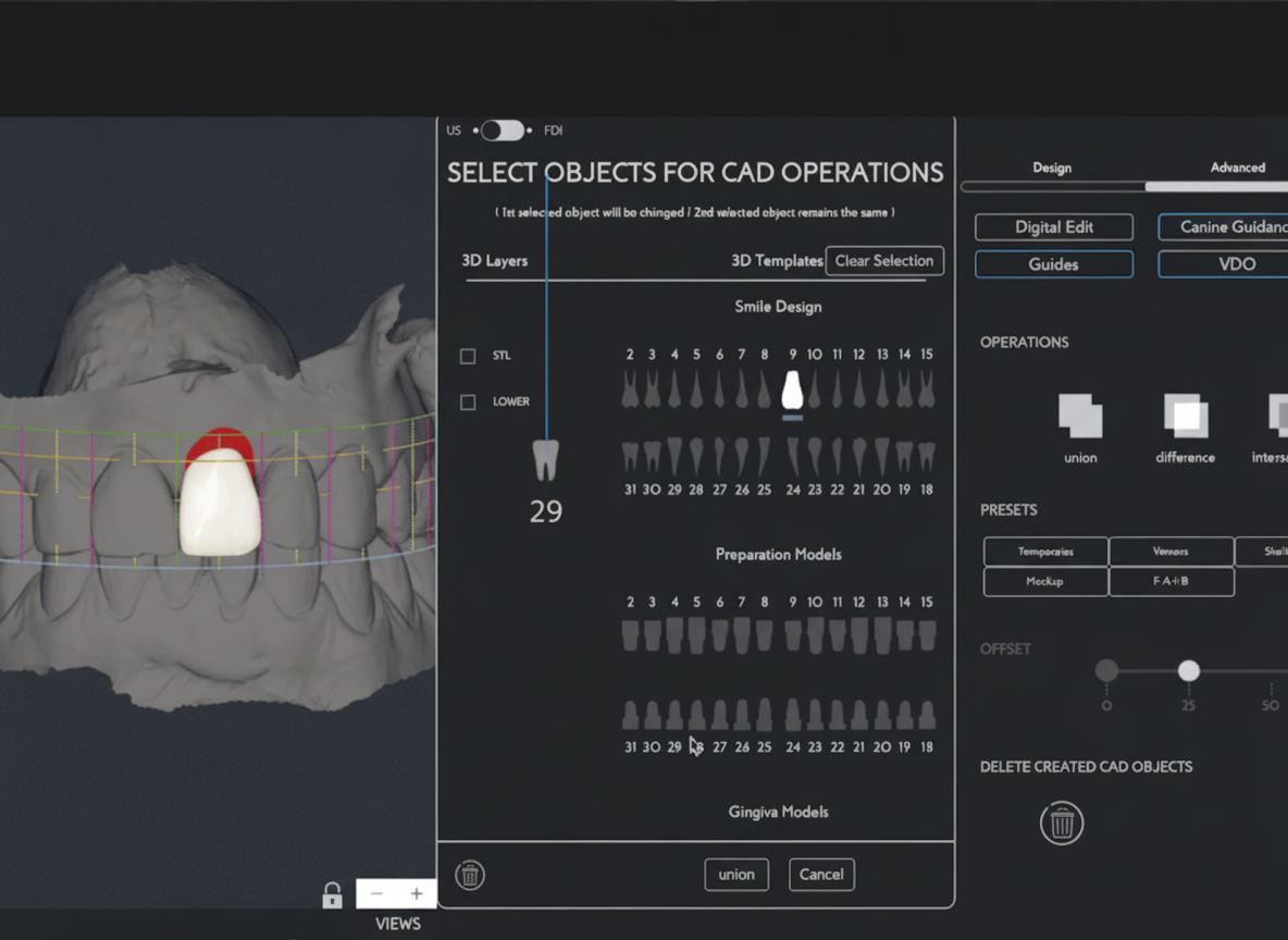
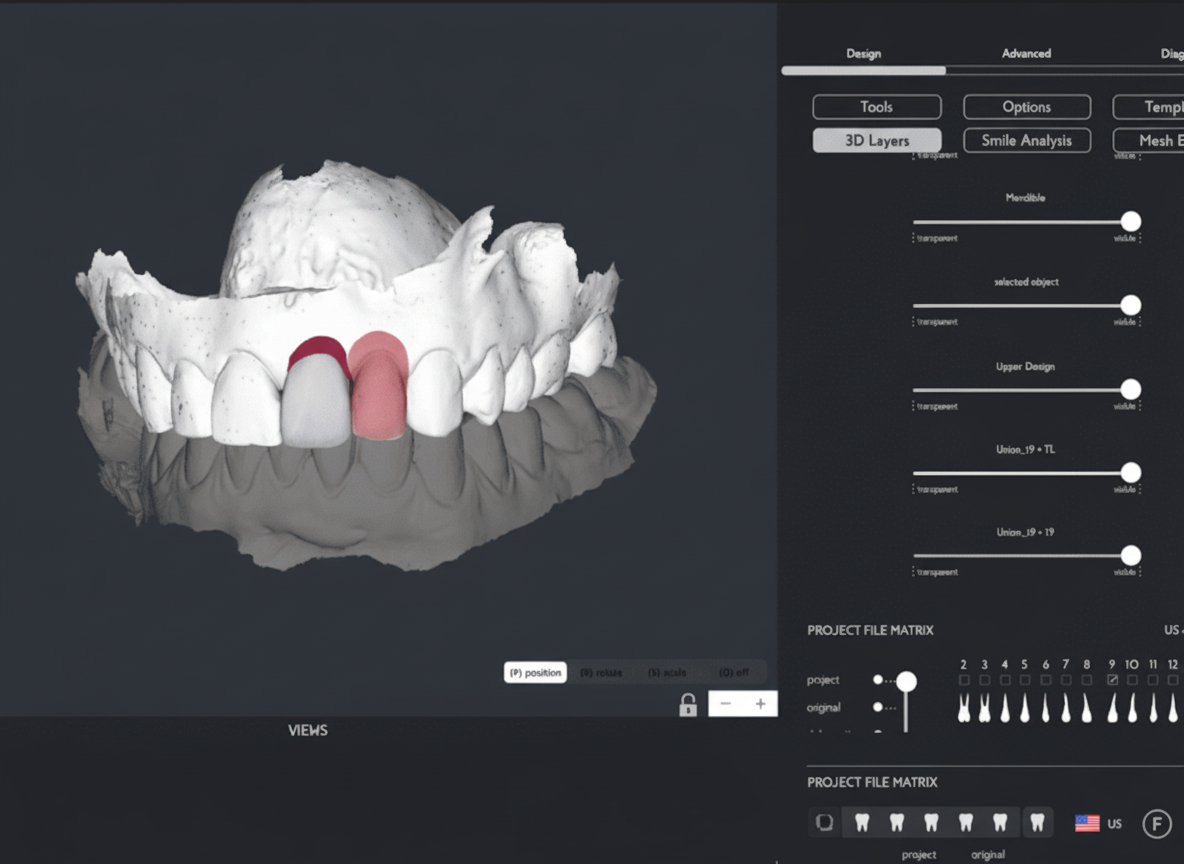
Step 6 — Union / Fuse (~2–3 min)
Generate the two fused STL files that the laboratory will use for biocopy. Confirm there are no open mesh edges before initiating the Fuse function — open edges prevent a watertight merge and will cause CAD import errors.
Option A: Crown and artificial gingiva merged into a single watertight solid.
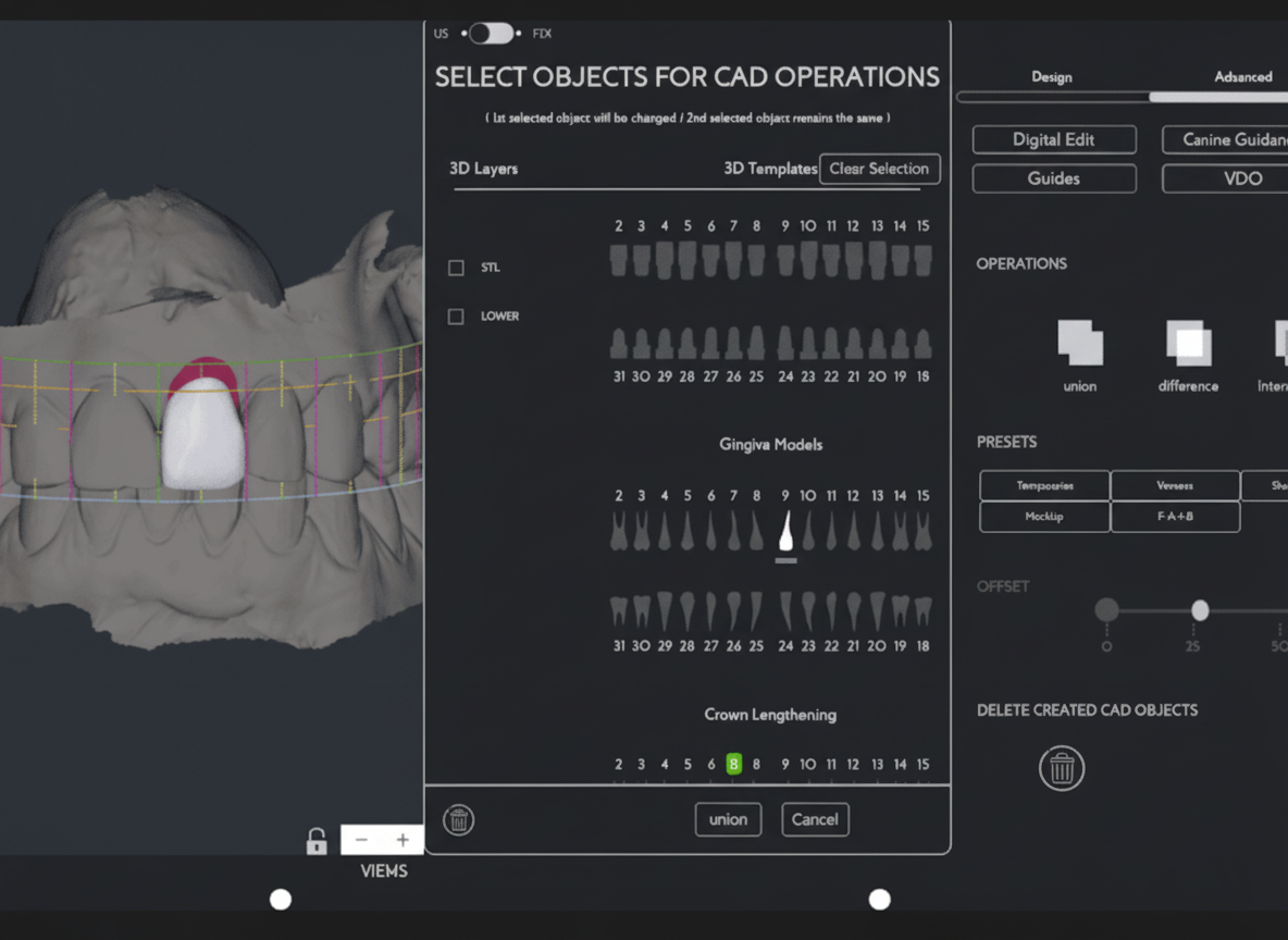
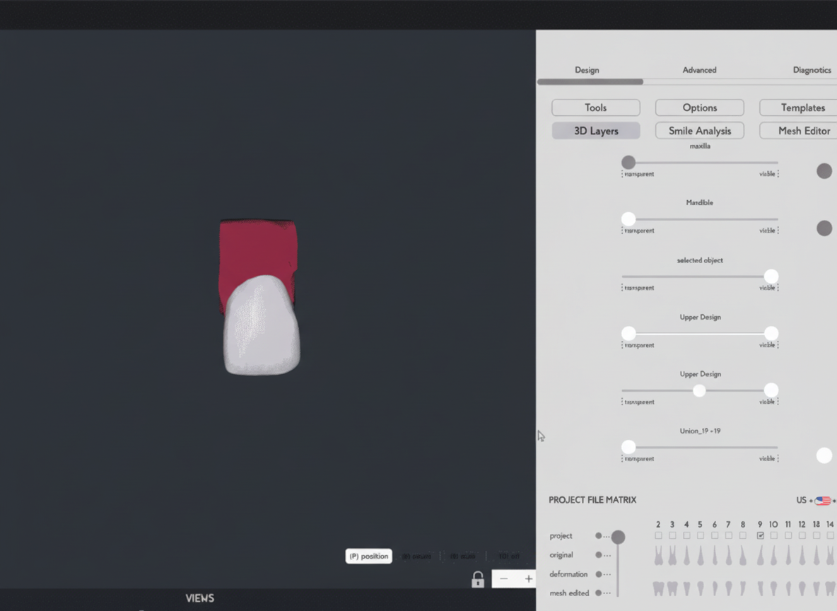
Option B: Crown, artificial gingiva, and upper arch scan model fused into a single file — giving the lab a complete spatial reference including the surrounding dentition and soft-tissue contours.
Step 7 — STL Export and Laboratory Handoff (~2 min)
Export all files as .STL. Send to the dental laboratory via email, SmileFy Drive, or any preferred file transfer method. All original and edited component files are also available for export separately, allowing the lab to work with individual meshes if their CAD workflow requires it.
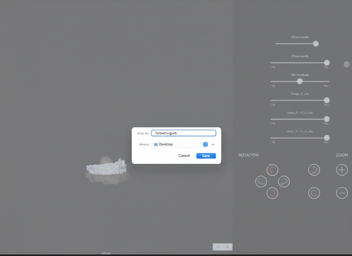
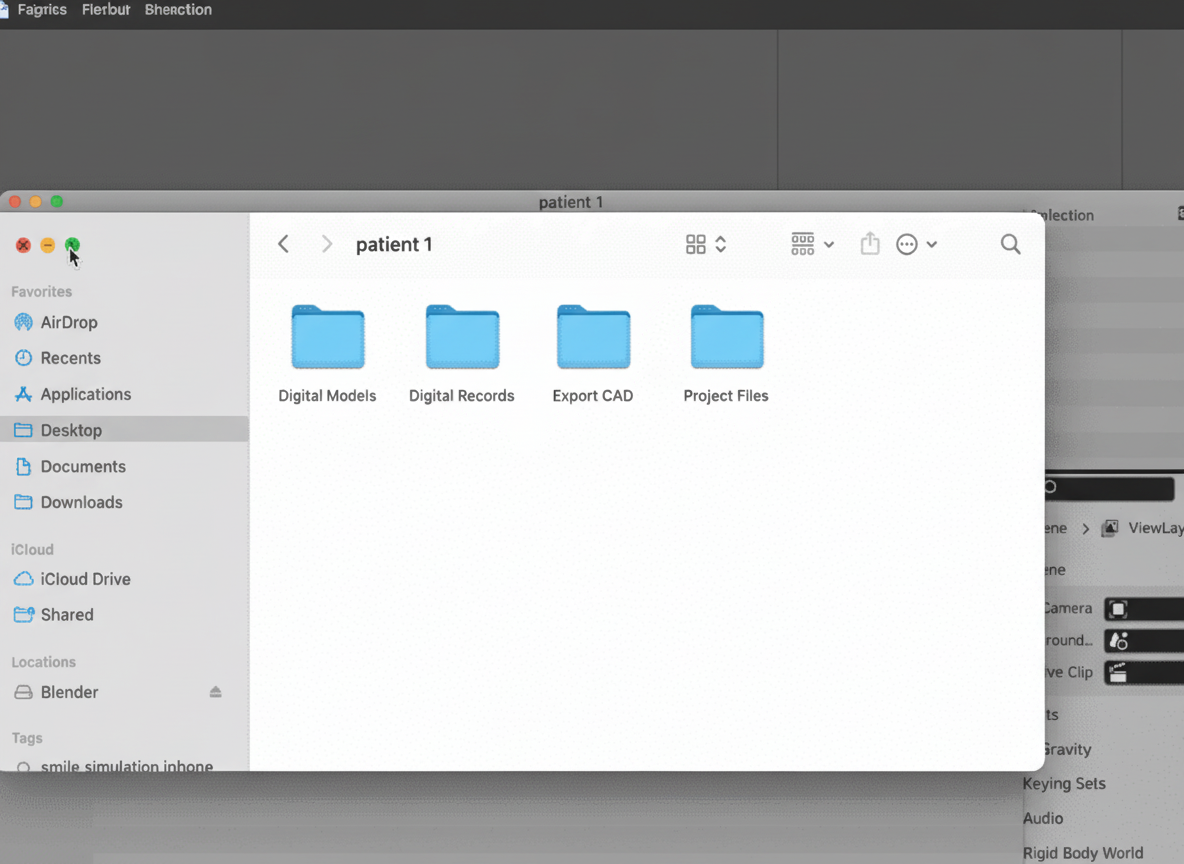
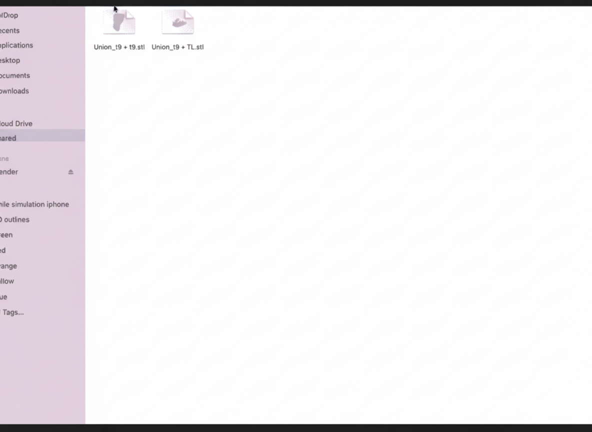
Recommended file naming: [PatientID]_[ToothNum]_[CrownGingiva/CrownGingivaModel]_[Date].stl
Which Fused STL to Send the Lab
Surgical implant guide → STL B (crown + gingiva + upper arch model) — the arch model provides the spatial reference needed for guide positioning and seating.
Crown temporary for immediate loading → STL A (crown + gingiva) as the biocopy reference. STL B optionally included for articulation reference.
Final crown with integrated artificial gingiva → STL A (crown + gingiva) as the primary biocopy reference. STL B for arch context if the lab is designing a custom abutment simultaneously.
When lab needs individual component files → Export the un-fused crown and gingiva STLs separately (available in the SmileFy export panel).
Conclusion
The complete design workflow (Steps 1–7) can be performed in a single chairside session of approximately 30–40 minutes. The use of chairside methods for planning the 3D Design of crown and artificial gingiva makes the workflow more assertive and the communication with the patient and the dental laboratory more efficient. With these fused STL files, it is possible to continue the digital dental path for manufacturing surgical implant guides, crown temps for immediate loading, and final crowns with artificial gingiva — all from a single unambiguous biocopy reference.
How this post will look when shared
smilefy.com
In-Office Crown and Artificial Gingiva Design for Replacement of Lost Interdental Papil…
A step-by-step digital workflow for designing a single crown with integrated artificial gingiva to eliminate…