Digitally Planning Gingivectomy Cases and Creating Gum Contouring Guides with SmileFy
Gummy smile and disproportionate gingival margins are among the most common esthetic complaints in cosmetic dentistry, yet traditional analog planning for gingivectomy and esthetic crown lengthening relies on subjective clinical judgment, blind probing to localise the cemento-enamel junction (CEJ), and indirect template fabrication — each step introducing cumulative error.
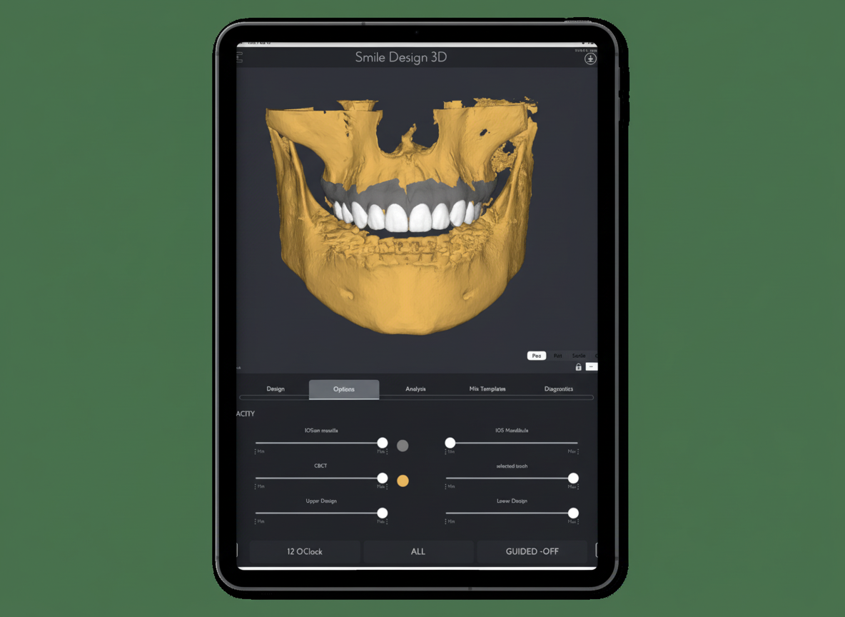
SmileFy's 3D Planning workflow integrates a calibrated frontal smile photograph, an intraoral scan, and a CBCT bone file to generate a facially-guided diagnostic wax-up from which a silicone gum-contouring guide can be directly fabricated, with biologic width safety checks built into the design process.
By incorporating the Perio Analysis functionality in the app, we can provide a simplified method of generating a reliable guide for predictable results from the diagnostic wax-up you've created in SmileFy. Moreover, using this feature helps you avoid unnecessary bone excision, which may cause root exposure and tooth sensitivity.
Workflow Summary
Import & Calibrate
Import frontal smile photo, upper arch IO scan (STL/OBJ), and CBCT bone file (DICOM) into SmileFy and align in a common coordinate frame.
Align 3D Smile Frame
Set the Smile Frame midline to the facial midline (not dental midline) and confirm the interpupillary line is horizontal.
Select Tooth Template
Choose a tooth shape template from SmileFy's library and adjust Height/position to define planned gingival margin levels.
Run Perio Analysis
Generate cross-sections through CBCT at each planned margin, measure CEJ-to-bone distance, and confirm ≥3 mm clearance for biologic width safety.
Export & Fabricate
Export STL, 3D print the diagnostic model, and fabricate a silicone gum-contouring guide for chairside margin transfer.
Facially-guided gingival margin placement with biologic width verification — no blind probing required. STL-to-guide workflow completed in a single digital session.
Key Definitions
Gingivectomy — The surgical excision of excess or diseased gingival tissue to expose a greater length of the clinical crown, reduce pocket depth, or reshape the gingival margin for esthetic purposes.
Esthetic Crown Lengthening (ECL) — A surgical procedure combining gingivectomy with selective osseous reduction when required, performed to increase visible clinical crown length for restorative or cosmetic indications.
Gingivoplasty — The reshaping of the gingival contour without removing a significant amount of tissue depth; typically an additive contouring of the existing gingival architecture.
CEJ (Cemento-Enamel Junction) — The anatomical boundary between the enamel of the crown and the cementum of the root; the most reliable fixed reference for measuring attachment levels and determining safe margins in crown lengthening.
Biologic Width — The combined dimension of the junctional epithelium (~0.97 mm) and the supracrestal connective tissue attachment (~1.07 mm) coronal to the alveolar crest; clinically approximated at 2–3 mm; violation triggers bone resorption, chronic inflammation, and recession.
CBCT / DICOM — Cone-Beam Computed Tomography producing a three-dimensional volumetric dataset exported in DICOM format; provides bone crest topography essential for biologic width assessment.
When Should You Use Digital Planning?
Analog gingivectomy planning — marking the gingival margin with a periodontal probe and scribing a freehand scallop — lacks repeatable reference to the facial midline, the CEJ, or the patient's smile-line aesthetics. Digital planning is indicated when:
Esthetic crown lengthening is planned in the visible smile zone (incisors to first premolars)
Margin levels must be harmonised across multiple teeth relative to the patient's lip line and facial midline
The CEJ is subgingival or uncertain from probing alone, and CBCT data is available to localise it non-invasively
Restorative margins are planned simultaneously (crown lengthening + ceramic preparation in one surgical appointment)
The patient needs to visualise and approve the planned outcome before irreversible surgery
Biologic width is at risk — particularly in cases where the gingival tissue is thin (biotype < 1.5 mm) or where probing depths are shallow
Three Required Files
You will need three files to create your gingivectomy guide:
Centered frontal smile photograph — Patient in Natural Head Position (NHP), 2x telephoto, ring-lit, lens at eye level, slightly open wide smile. Minimum resolution: 1200 x 900 px. Image must show both pupils for calibration.
Upper intraoral scan — Export from your scanner (Medit, TRIOS, 3Shape, or equivalent) in STL or OBJ format. Full arch from second molar to second molar with intact interproximal surfaces.
CBCT bone file — Upper jaw DICOM dataset. Recommended: FOV 8 x 8 cm centred on the maxillary anterior/premolar region; voxel size ≤ 0.2 mm.
Step-by-Step Digital Planning Workflow
Step 1 — Import and Calibrate Photo, IO Scan, and CBCT
Import the frontal JPEG, upper arch IO scan (STL/OBJ), and CBCT DICOM into SmileFy. Use the calibration tools to align all three data sources in a common coordinate frame. Confirm alignment by verifying that the incisal edges in the IO scan coincide with the incisal edge positions visible in the photograph.
Watch-out: If the patient's head is tilted in the photograph (camera not level, or patient not in NHP), the 3D Smile Frame will be set to a canted reference — all margin targets and midline positions will be incorrect. Retake the photograph rather than correcting the cant in-app.
Step 2 — Align the 3D Smile Frame Facially
Confirm the interpupillary line is horizontal in the photograph. Set the 3D Smile Frame midline to the patient's facial midline (glabella-nasal tip-philtrum-chin axis), not to the dental midline. Select the number of teeth to include in the design (typically 8–10 for a full anterior smile zone).
Watch-out: Setting the Smile Frame midline to the dental midline rather than the facial midline will cause the planned margin levels to be asymmetric relative to the face, not to the dentition.
Step 3 — Select Tooth Library Template and Adjust Position
Open the SmileFy tooth library. Select a tooth shape template that matches the patient's natural morphology — size, gingival embrasure form, and proximal profile. Fine-tune Frame > Height so that the gingival margin of each template tooth aligns with the planned post-gingivectomy margin level.
Watch-out: Over-selecting a template with a very long clinical crown form will place the planned margin too apically, potentially violating the biologic width. Start with a proportionate template (height-to-width ratio 75–85% for central incisors).
Step 4 — Run Perio Analysis: Cross-Section, Measure CEJ-to-Bone, Adjust Margin
Open the Perio Analysis module. The software superimposes the CBCT bone data on the IO scan and the facial photo in a common 3D space. For each tooth in the treatment zone, generate a labial cross-section through the CBCT volume at the planned facial margin position.
The cross-section displays: (a) the bone crest, (b) the estimated CEJ position, and (c) the planned margin level from the Smile Frame template.
Green zone — margin ≥ 3 mm from bone crest: biologic width is safe, soft tissue gingivectomy only is sufficient.
Yellow zone — margin 2–3 mm from bone crest: borderline; consider reducing the planned margin gain or staging.
Red zone — margin < 2 mm from bone crest: biologic width will be violated; osseous reduction is required.
Step 5 — Export STL, 3D Print, and Fabricate the Silicone Guide
Once the Perio Analysis confirms biologic width safety for all teeth in the treatment zone, export the 3D wax-up as an STL file. Import into your 3D printing software and print the diagnostic model in rigid biocompatible resin. From the 3D printed model, vacuum-form or manually press a silicone index over the cervical region to create the gum-contouring guide.
At the surgical appointment, seat the silicone guide on the teeth. Use a periodontal probe or a #15 scalpel to mark the new gingival margin at the guide edge. Remove the guide and complete the gingivectomy following the marked scallop.
Mini Case Example — Upper Anterior Esthetic Crown Lengthening
Patient: 28-year-old female presenting with a gummy smile (4.5 mm gingival display at maximum smile), short upper central incisors (clinical crown height 7.5 mm, mesiodistal width 8.8 mm — height-to-width ratio 85%), and symmetric altered passive eruption (APE). CBCT confirmed adequate bone volume; no root proximity concerns.
Pre-op gingival display at max smile — 4.5 mm (target: ≤ 2 mm)
Pre-op clinical crown height (centrals) — 7.5 mm
Pre-op CEJ-to-bone crest distance (centrals) — 1.0 mm (biologic width intact — thin gingival biotype)
Planned gingivectomy gain (centrals) — 2.0 mm (margin moved 2.0 mm apically)
Planned margin-to-bone distance (post-gingivectomy) — 3.0 mm — within safe threshold (green zone)
Osseous reduction required? — No — all teeth in green zone. Soft tissue gingivectomy only.
Post-op clinical crown height (planned) — 9.5 mm (height-to-width ratio 108% — within natural range)
Post-op gingival display at max smile (predicted) — 2.0–2.5 mm — within esthetic range
Outcome (6-week review): Gingival margin position matched the planned levels within 0.5 mm bilaterally. No signs of biologic width violation (no bone resorption on periapical radiograph, no recession at 6 weeks). Patient reported high satisfaction with the esthetic outcome.
Advantages of a Digital Gingivectomy Workflow
Non-invasive CEJ localisation — Identifies the CEJ from the CBCT without probing under anaesthesia, allowing biologic width assessment to be completed pre-surgically.
Avoids unnecessary bone excision — Perio Analysis identifies which teeth require osseous reduction before the flap is raised, preventing over-reduction and root exposure.
Facially-guided margin placement — Gingival margins are positioned relative to the facial midline, lip line, and tooth proportions simultaneously — not just relative to the existing gingival architecture.
Patient co-planning — The 3D digital preview allows the patient to visualise and approve the planned outcome, improving treatment consent quality and managing expectations before irreversible surgery.
Simultaneous gingival and restorative planning — Crown lengthening and ceramic preparation margins can be planned in the same digital session.
Reproducible guide fabrication — The STL export and 3D printed model produce a silicone guide with defined margin levels that can be reproduced or modified digitally if the clinical plan changes.
Frequently Asked Questions
Q: What files do I need to start?
You need three files: (1) a frontal smile JPEG photograph (≥ 1200 x 900 px, NHP, ring-lit); (2) the upper arch intraoral scan in STL or OBJ format; and (3) the CBCT upper jaw DICOM folder (voxel size ≤ 0.2 mm recommended).
Q: Which intraoral scanners are compatible?
SmileFy accepts standard STL and OBJ files from all major scanners including Medit i500/i700/i900, TRIOS 3/4/5, 3Shape, iTero Element series, and Planmeca Emerald.
Q: How does SmileFy respect biologic width?
The Perio Analysis module measures the distance from the planned gingival margin to the alveolar bone crest in the CBCT cross-section. The clinician manually confirms ≥ 3 mm before exporting. SmileFy displays a colour zone (green/yellow/red) for each tooth.
Q: Can I use Perio Analysis without a CBCT?
No. The CBCT DICOM dataset is required to localise the CEJ and measure the bone crest distance. Without CBCT, the CEJ must be localised clinically (probing under anaesthesia).
Q: What gets exported from SmileFy?
SmileFy exports the 3D wax-up as an STL file. This is printed in rigid biocompatible resin, and a silicone index is pressed over the cervical region to create the gum-contouring guide.
Video Tutorial
To learn more about planning gingivectomy cases with SmileFy, watch the tutorial where Dr. Diogo Alves explains the Perio Analysis feature and puts it into practice.
How this post will look when shared
smilefy.com
Digitally Planning Gingivectomy Cases and Creating Gum Contouring Guides with SmileFy
SmileFy's 3D Planning workflow integrates CBCT, intraoral scan, and facial photography to create facially-gui…